
What new sensors do we have Fall 2026?
Thanks to the Engineering Excellence Fund, we acquired over 50 new sensors the summer of 2026 that are inventoried, tested, and ready for student checkout Fall 2026.
Here's what's new for Fall 2026!
Everything below is available for checkout from the ITLL Electronics Center (ECCE 167)!
Incremental Rotary Encoders (QTY 2)

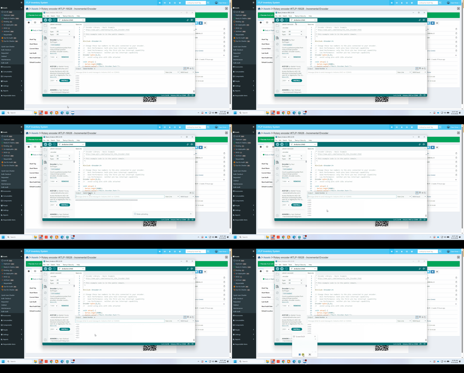

Description above from: https://www.pjrc.com/teensy/td_libs_Encoder.html?#
GIF made by yours truly (Claire Porter). I'm turning the encoder shaft CW, then CCW, and you can see the output increment, then decrease.
CODE (Arduino)
I used this library on an Arduino Uno:

I gave the encoder 5V via brown (5V) and blue (GND) wires, and plugged black (OUT A) and white (OUT B) into digital pins 5 and 6. I also tested other pins (2 and 3). I plugged the orange wire (OUT Z) into a random digital pin (8), but did not call it in my code.
TROUBLESHOOTING
1. Initially I couldn't get Basic.ino to run. I got the following errors:
direct_pin_read.h:8:56: note: in definition of macro 'DIRECT_PIN_READ' #define DIRECT_PIN_READ(base, mask) (((*(base)) & (mask)) ? 1 : 0)
FIX: I uninstalled and installed the library.
2. I thought 2000 pulses = 1 revolution, but I'm finding that 1 revolution ~ 8000 pulses. I'm using pins 2 and 3 for black and white wires. Even weirder - when I switch to different pins, I find that 1 revolution ~ 70 pulses. I thought that the resolution of this encoder was 2000 pulses per revolution. HALP!
FIX: It turns out that on an Arduino Uno, pins 2 and 3 are dedicated interrupt pins, which is a good thing for counting pulses as quickly as possible. You want to use these pins (and if you aren't using an Arduino Uno, check and see which are the hardware interrupt pins for your board). The code is just incrementing when the signals read on either pin 2 or 3 change, and since A and B (output from this quadrature encoder) change 4 times per change in position (the laser shines through a new window on the internal wheel). This is because the waveform generated by A is 90 degrees offset from B, or equivocally, the the phase offset of B relative to A is 1/4 the period of A. Talk to Claire or Nora if you are confused and would like a whiteboard demonstration of how a quadrature encoder works.
When I tested other pins:, such as 5 and 6, and 11 and 10, I found ~70 PPR. Note that if you switch the white and black wire, this just switches whether CW or CCW rotation corresponds to the encoder count increasing. Don't use pin 13 (built in LED); the counter misses pulses likely due to hardware conflicts.
Linear Actuators (QTY 4)
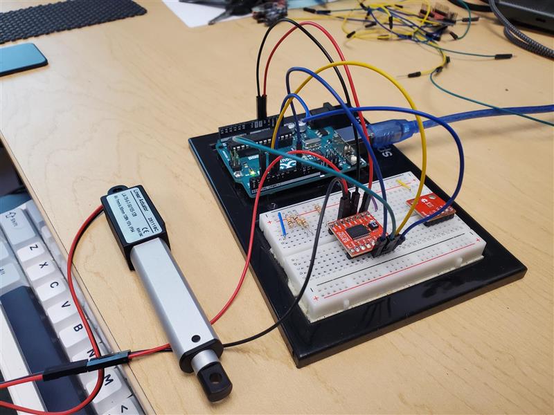
These little 50mm linear actuators are from DF Robot will be a great asset to a project requiring controlled linear movement. Although they nominally take 6V, I was able to run them using 5V on an Arduino Uno. I interfaced with a Sparkfun DC Motor driver, and was impressed at the force they delivered. Even when pushing fairly hard with my finger, the actuator was able to extend fully. These are awesome. Note that you will need to use a driver, or else construct your own H-bridge circuit to retract them after they've extended.
SENSOR
(ADD PHOTO)
PM2.5 Air Quality Sensor and Breadboard Adapter Kit
Link to sensor:
Code link:
Arduino Code | PM2.5 Air Quality Sensor | Adafruit Learning System
Use case, any helpful tips?
The PM2.5 Air Quality Sensor provides real-time, reliable measurement of PM2.5 dust concentrations! (PM2.5 refers to particles that are 2.5 microns or smaller in diameter.) This sensor uses laser scattering to radiate suspending particles in the air, then collects scattering light to obtain the curve of scattering light change with time. The microprocessor calculates equivalent particle diameter and the number of particles with different diameter per unit volume.
Troubleshooting (document any issues you ran into and their resolution):
Issue: The code provided in the link is set up to be able to handle both hardware and software serial communication.
Fix: Due to this when using that code, the user needs to uncomment out a few commented-out lines. These lines are the pin set ups and the serial communication lines. User needs to make sure to comment / uncomment a few lines according to what type of serial communication they are using.
SENSOR
(ADD PHOTO)
Adafruit 9-DOF Orientation IMU Fusion Breakout - BNO085
Link to sensor:
Code link:
Overview | Adafruit 9-DOF Orientation IMU Fusion Breakout - BNO085 | Adafruit Learning System
Use case, any helpful tips?
I2C Wiring:
- Connect board VIN (red wire) to Board 3V
- Connect board GND (black wire) to Board GND
- Connect board SCL (yellow wire) to Board SCL
- Connect board SDA (blue wire) to Board SDA
Troubleshooting (document any issues you ran into and their resolution):
Issue: When using I2C communication, the library needed to use the IMU is too large and complex to fit onto the Arduino Uno.
Fix: To use this sensor with an Arduino Uno you are to use UART communication. This means you cannot use the nice I2C chord provided with the sensor. Instead, you have to plug the header pins into a breadboard and manually set up each pin.
PinoutsPINOUTS FOR UART
VIN ---> 5V
GND ---> GND
SDA ---> Digital Pin 2
P0 ---> 5V
No other pins need to be connected
CODE FOR UART
#include <SoftwareSerial.h>
#include <Adafruit_BNO08x_RVC.h>
// Connect Arduino Pin 2 to BNO085 SDA (TX Out)
SoftwareSerial softwareSerial(2, 3);
Adafruit_BNO08x_RVC rvc;
void setup() {
Serial.begin(115200);
while (!Serial) delay(10);
Serial.println("Adafruit BNO08x RVC Test!");
softwareSerial.begin(115200);
// Pass our software serial port to the RVC library
if (!rvc.begin(&softwareSerial)) {
Serial.println("Could not find sensor. Check wiring and P0 pin!");
while (1) delay(10);
}
Serial.println("Sensor Found! Starting stream...");
}
void loop() {
BNO08x_RVC_Data heading;
// Read the incoming continuous data stream
if (rvc.read(&heading)) {
Serial.print("Yaw: ");
Serial.print(heading.yaw);
Serial.print(" Pitch: ");
Serial.print(heading.pitch);
Serial.print(" Roll: ");
Serial.println(heading.roll);
}
}
Adafruit Ultimate GPS PA1616S
Link to sensor page: https://www.adafruit.com/product/746
*add photo
Use case, any helpful tips?:
The Adafruit Ultimate GPS module gives any microcontroller project access to location, time, date, speed and heading data---pulled directly from GPS satellites.
Common Uses:
- asset/vehicle trackers
- data loggers with timestamps
- geotag sensor readings
- drones/robotics needing position feedback
Very Helpful Documentation I referenced
I particularly found the direct computer wiring, computer Arduino wiring and, computer Arduino parsing helpful. Each section tests three stages of working with the GPS module and each have a distinct purpose:
Direct Computer Wiring
This bypasses the Arduino's microcontroller entirely and routes the GPS straight to the USB-to-serial chip (using a blank sketch) --> RAW VERIFICATION
* add wiring photo
* add blank sketch
Troubleshooting
- Issue: Serial monitor shows garbled serial output instead of readable NMEA sentences
Becuase the data looks crazy here but nothing is actually introduced to the wiring we know the problem is the GPS hardwire or our wiring and NOT the code.
ex) :
AI5 ⸮235953.800,V,,,,,0.00,0.00,050180,,,N*42
⸮⸮⸮⸮⸮⸮⸮⸮⸮⸮⸮⸮⸮⸮$GPGGA,000518.800,,,,,0,0,,,M,,M,,*4C
instead of
$GPGSA,A,1,,,,,,,,,,,,,,,*1E
$GPRMC,000518.800,V,,,,,0.00,0.00,050180,,,N*45
$GPGGA,000519.800,,,,,0,0,,,M,,M,,*4D
$GPGSA,A,1,,,,,,,,,,,,,,,*1E
$GPRMC,000519.800,V,,,,,0.00,0.00,050180,,,N*44
- Fix:
- confirm correct sketch is uploaded (empty sketch, push arrow on arduino uno sketch page to upload)
- confirm serial monitor baud is set to 9600
- check for incorrect or loose wiring of TX/RX on the microcontroller as well as the sensor
Breakout Arduino Wiring
Now that we have completed a sanity check that the sensor works as expected without other software variables, breakout Arduino wiring will test the Arduino's own microcontroller reads the incoming serial stream. This will prove that the full data path works.
GPS --> Arduino --> USB --> Computer
I used this library on an Arduino Uno and the example sketch GPS_SoftwareSerial_ECHO:
* add photo of library name and example sketch
* add photo of wiring
Troubleshooting
- Issue: Serial monitor doesn't output readable NMEA sentences
ex) : ?????????????????????????????????
instead of
Software3*30
$PMTK705,AXN_2.51_3339_17112000,0004,1616S,1.0*56
⸮Software Serial GPS Test Echo Test
Get version!
$GPGGA,000016.799,,,,,0,0,,,M,,M,,*48
$GPGLL,,,,,000016.799,V,$PMTK705,AXN_2.51_3339_17112000,0004,1616S,1.0*56
$GPGGA,000018.799,,,,,0,0,,,M,,M,,*46
$GPGLL,,,,,000018.799,V,N*74
$GPGSA,A,1,,,,,,,,,,,,,,,*1E
$GPGSV,1,1,00*79
$GPRMC,000018.799,V,,,,,0.00,0.00,050180,,,N*4F
1. Fix:
- There is a rate mismatch between SoftwareSerial and teh GPS module
- confirm serial monitor baud is set to 115200
- confirm RX and TX are not switched and your code initializations match your physical wiring
Breakout Arduino Parsing
Up until now, we have just been displaying raw text. This is where we will use a library to interpret the NMEA sentences into usable variables like latitude, longitude, speed, time, fix status etc.
I used the same library and wiring as the previous wiring section on an Arduino Uno but now we will use the example sketch GPS_SoftwareSerial_Parsing:
* add photo of library name and example sketch