
What new sensors do we have Fall 2026?
Thanks to the Engineering Excellence Fund, we acquired over 50 new sensors the summer of 2026 that are inventoried, tested, and ready for student checkout Fall 2026.
Here's what's new for Fall 2026:2026!
Everything below is available for checkout from the ITLL Electronics Center (ECCE 167)!
Incremental Rotary Encoders (QTY 2)


Description above from: https://www.pjrc.com/teensy/td_libs_Encoder.html?#
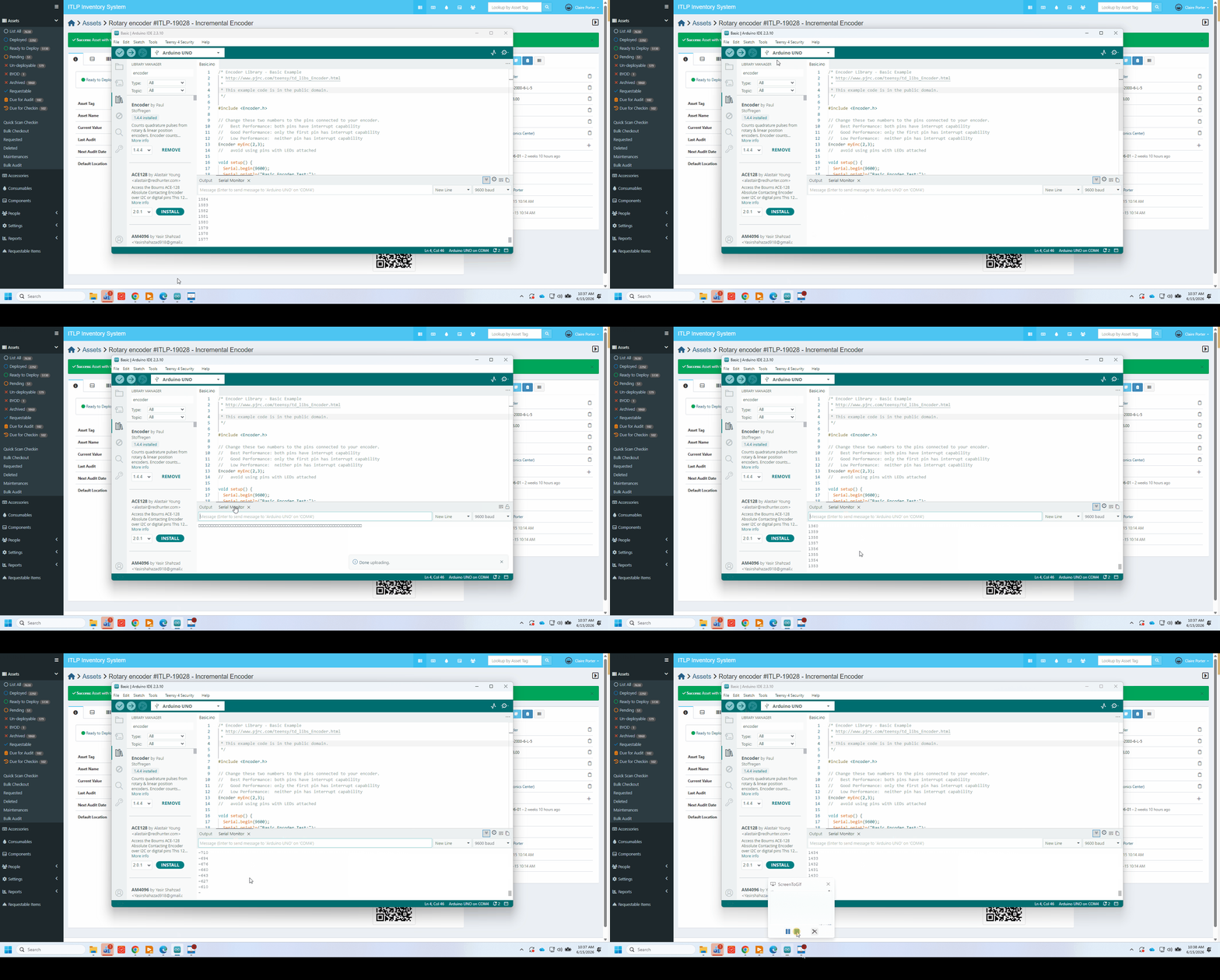
GIF made by yours truly (Claire Porter). I'm turning the encoder shaft CW, then CCW, and you can see the output increment, then decrease.
CODE (Arduino)
I used this library on an Arduino Uno:

I gave the encoder 5V via brown (5V) and blue (GND) wires, and plugged black (OUT A) and white (OUT B) into digital pins 5 and 6. I also tested other pins (2 and 3). I plugged the orange wire (OUT Z) into a random digital pin (8), but did not call it in my code.
TROUBLESHOOTING
1. Initially I couldn't get Basic.ino to run. I got the following errors:
direct_pin_read.h:8:56: note: in definition of macro 'DIRECT_PIN_READ'
#define DIRECT_PIN_READ(base, mask) (((*(base)) & (mask)) ? 1 : 0)
FIX: I uninstalled and installed the library.
2. I thought 2000 pulses = 1 revolution, but I'm finding that 1 revolution ~ 8000 pulses. I'm using pins 2 and 3 for black and white wires. Even weirder - when I switch to different pins, I find that 1 revolution ~ 70 pulses. I thought that the resolution of this encoder was 2000 pulses per revolution. HALP!
FIX: It turns out that on an Arduino Uno, pins 2 and 3 are dedicated interrupt pins, which is a good thing for counting pulses as quickly as possible. You want to use these pins (and if you aren't using an Arduino Uno, check and see which are the hardware interrupt pins for your board). The code is just incrementing when the signals read on either pin 2 or 3 change, and since A and B (output from this quadrature encoder) change 4 times per change in position (the laser shines through a new window on the internal wheel). This is because the waveform generated by A is 90 degrees offset from B, or equivocally, the the phase offset of B relative to A is 1/4 the period of A. Talk to Claire or Nora if you are confused and would like a whiteboard demonstration of how a quadrature encoder works.
When I tested other pins:, such as 5 and 6, and 11 and 10, I found ~70 PPR. Note that if you switch the white and black wire, this just switches whether CW or CCW rotation corresponds to the encoder count increasing. Don't use pin 13 (built in LED); the counter misses pulses likely due to hardware conflicts.
Linear Actuators (QTY 4)
TThese little 50mm linear actuators are from DF Robot will be a great asset to a project requiring controlled linear movement. Although they nominally take 6V, I was able to run them using 5V on an Arduino Uno. I interfaced with a Sparkfun DC Motor driver, and was impressed at the force they delivered. Even when pushing fairly hard with my finger, the actuator was able to extend fully. These are awesome. Note that you will need to use a driver, or else construct your own H-bridge circuit to retract them after they've extended.