
ATMEGA328 Through-Hole DIP28
ATMEGA328P
Below is the pinout for the Through-Hole part in the Arduino Uno R3.

In order to program this particular part from factory settings, you must bootload the microcontroller. Bootloading the microcontroller(mcu) will effectively load the equivalent of the Arduino operating system onto the integrated circuit. You need this because the mcu can be used for a variety of things, the software we are choosing to use, requires some setup. Think of it as telling the microcontroller, when you upload code, this is the language and here is how I want it to be used. We will start by preparing the programming Arduino.
Arduino Preparation
- Plug Arduino dev board into computer and open Arduino IDE
- For our examples, I will be using the Legacy IDE (1.8.19) and an Arduino Uno.
- Navigate to the File menu, select examples and open the Arduino as ISP sketch.
-
- Upload the sketch to the programming Arduino.

Circuit Preparation
In order to bootload we are going to use an already functional Arduino Uno; this is not the only way to accomplish this, it is just the way we are documenting today.
The pins required to bootload the target microcontroller are listed below:
- Physical Pin 1, named PC6, which functions as PCINT14 and RESET, is required to reset the mcu during the bootloading process. It is connected to the chip select SPI pin on the programming Arduino (digital 10). This pin also has a 10k pull-up resistor.
- Physical Pin 7, named VCC, which functions as power input to the mcu, is required to power on the device.
- Physical Pin 8, named GND, which functions as ground for the mcu, is required to complete the circuit.
- Physical Pin 9, named PB6, which functions as PCINT6, Crystal Pin 1, and Timer / Oscillator Pin 1, is used with one pin of a 16Mhz crystal and capacitor to create the clock signal.
- Physical Pin 10, named PB7, which functions as PCINT7, Crystal Pin 2, and Timer / Oscillator Pin 2, is used with the other pin the same 16Mhz crystal and second capacitor to create the clock signal.
- Physical Pin 17, named PB3, which functions as SPI protocol Manager Out pin, is tied to the SPI pins on the programming Arduino, digital 11.
- Physical Pin 18, named PB4, which functions as SPI protocol Manager In pin, is tied to the SPI pins on the programming Arduino, digital 12.
- Physical Pin 19, named PB5, which functions as SPI protocol Clock pin, is tied to the SPI pins on the programming Arduino.
- For the purpose of testing, I have placed a debug resistor on this pin, it is conveniently linked to Arduino digital pin 13 and thus does a great job of confirming programming by way of the BLINK code.
- Physical Pin 20, named AVCC, which functions as the ADC reference voltage, should be tied to Vcc.
- Physical Pin 22, named GND, which functions as ground, is required to be tied to ground.
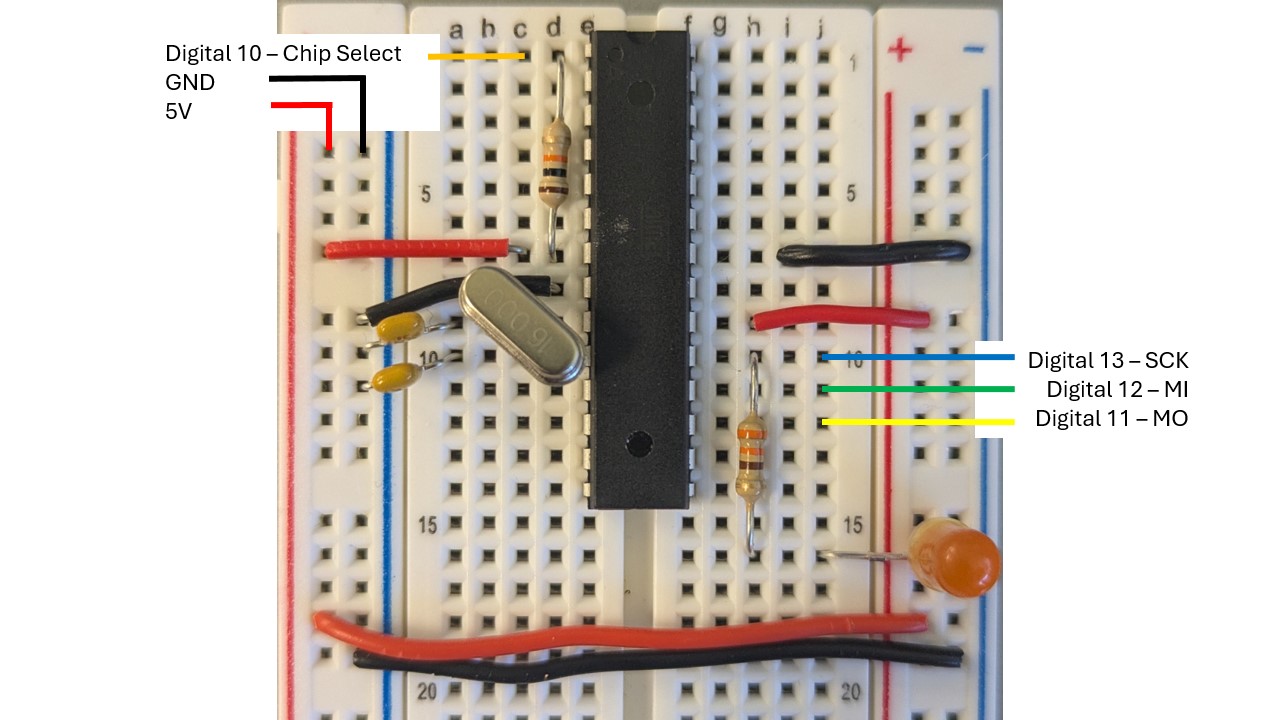
Bootloading the target Arduino
Now that the connections are made, return to the software. Navigate to the tools menu and change your programmer to Arduino as ISP.
Then select "Burn Bootloader".

The software will present this message while bootloading.

If successful you will be met with this message.

Uploading sketches
Open whatever sketch you wish to upload, and use the sketch menu to "Upload Using Programmer".