Measuring distance/proximity
The Electronics Center has a wide variety of object/distance detection sensors available for your project needs.
Everything listed below is available for checkout from the Electronics Center (ECCE 167).
If you just need to sense if an object has moved (e.g., counting fan blade rotations or detecting a waving hand):
- Passive Infrared (PIR) sensor
- IR LED & transceiver (nice for "photogate" or "beam break" applications)
- Hall sensor (good for detecting magnets)
If you need to quanitfy or measure a distance to an object, we recommend:
- Ultrasonic Sensor (HC-SR04)
- SHARP 2Y0A02 IR Sensor
- LiDAR
- Passive Infrared (PIR) Sensors
- Ultrasonic Sensor
- Measuring distance/proximity
- IR LED & transceiver
- Hall Sensor (AH1815, from Treston)
Passive Infrared (PIR) Sensors
Overview
PIR or Passive Infrared Sensors are commonly used in projects where students want a device capable of motion detection. These sensors detect movement by measuring changes in infrared radiation emitted by warm objects, such as people or animals, within their field of view. These sensors are known as "passive" sensors, as they merely listen to changes in energy, and do not emit any signals themselves. This passive characteristic makes them ideal for low power applications.
Staff at the ITLL tested the detection range of these sensors along with doing some research and found it could sense motion up to approximately 23 feet or 7 meters (depending on model and conditions). You may have seen these sensors before as they are commonly used for automatic lights, interactive exhibits, or security alarms. At the ITLL, you can find them controlling the lights within our lab spaces to save energy.
Students are welcome to come by and check out sensors from the Electronics Center. These are the sensors you can check out from the ITLL: link to inventory . If you do not see a sensor listed feel free to come in and chat with an Engineer about you project.
What is a PIR Sensor?
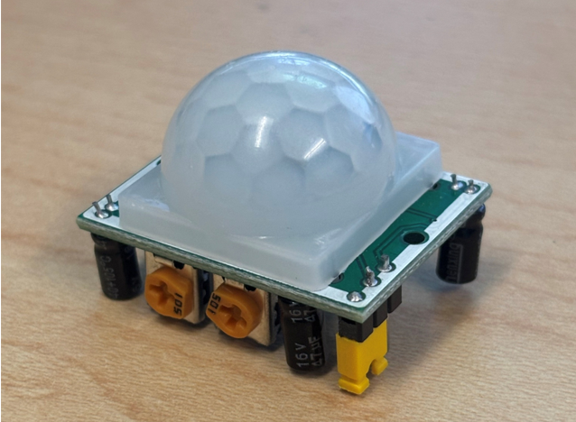
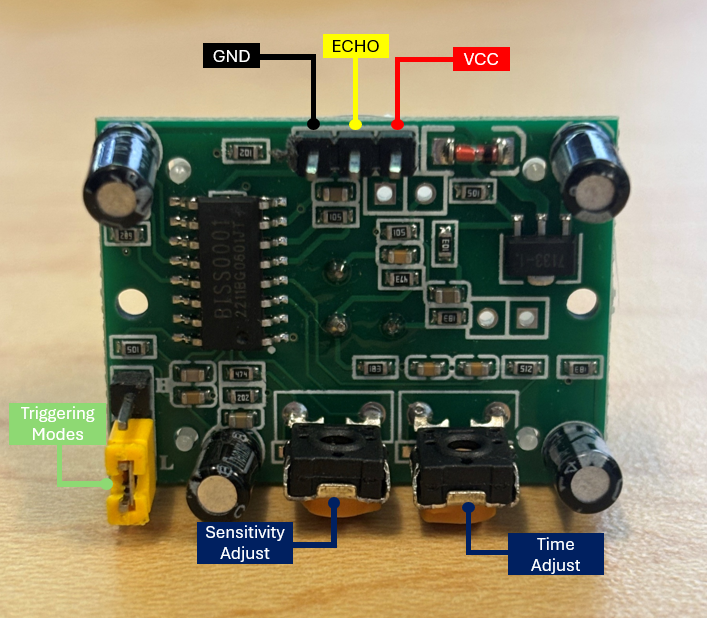
A PIR sensor comes with a small white dome shaped lens on top of the PCB. This lens, the Fresnel lens, helps focus light from any direction to the small pyroelectric sensor underneath. When motion occurs, half of this sensor detects a change in IR before the other, and the difference causes a signal change (from LOW to HIGH). These sensors also include a sensitivity and time delay adjustment potentiometer. Which allow you to change the range or distance the sensor can detect, and how long the sensor remains active (before switching back from HIGH to LOW). Below you can find an image labeling the potentiometers.
Wiring the Sensor
Important: Look up your specific sensors pinout and input voltage as they can differ. The pinout for the sensor we used in this demo was...
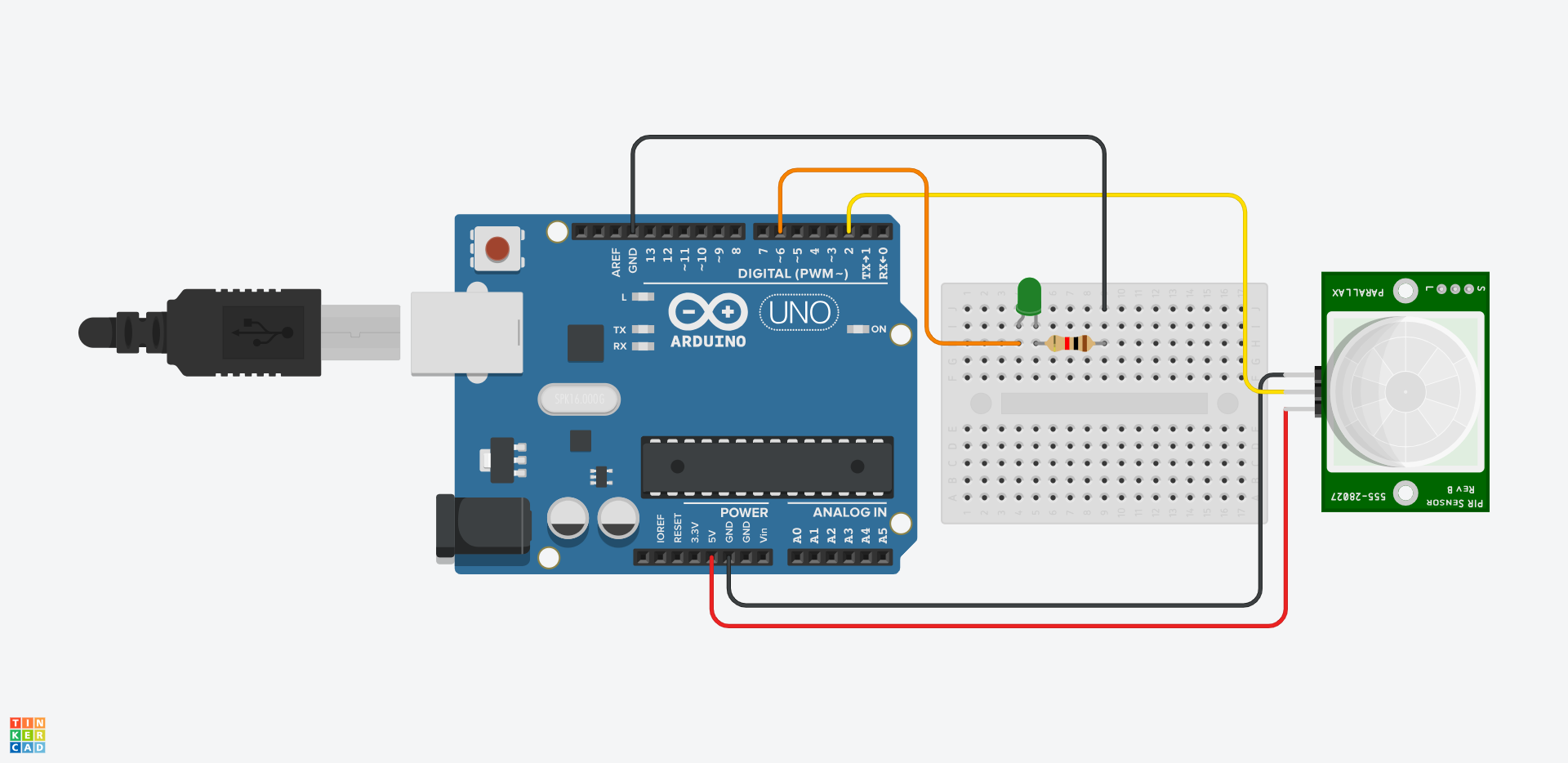
Example circuit setup:
- PIR sensor output connected to Arduino digital pin 2, VCC connected to 5V, and GND connected to GND.
- LED connected to Arduino digital pin 6 and 330 ohm resistor (resistor band color is different on picture).
Troubleshooting
- If sensor reading always HIGH or ON
- Sensor may be warming up (10-60 seconds after being turned on)
- Reduce sensitivity with potentiometer
- Ensure stable power supply - If no output changes
- Verify correct wiring
- Use Serial Monitor to debug readings - If false triggering
- Avoid pointing sensor at heat source (like a vent)
- Ensure no vibration of sensor mount
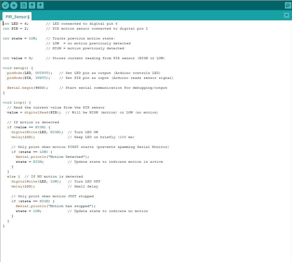
Simple Code
|
Ultrasonic Sensor
Overview
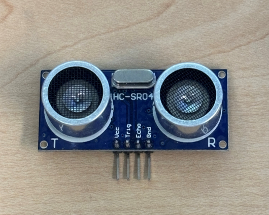
Ultrasonic Sensors are a common form of proximity and distance sensors used in a wide variety of different projects. These sensors feature both an emitter (trigger) which releases an ultrasonic sound wave, and a receiver (echo) which reads the ultrasonic sound wave as it returns.
Claire suggested edits:
In the Overview, provide the range and accuracy of these sensors. I'd get rid of the first sentence. Second sentence is great because it explains the working principle.
I actually had something written up about these sensors elsewhere, and I will paste my sentences here. Feel free to take 'em or leave 'em:
These sensors can detect objects within a range of 2 cm - 4 m with a ranging accuracy of up to 3mm. One thing to note is that they have a measure angle of 15 degrees, so they do well at measuring objects directly in front of the sensor. For most applications, this is favorable.

Helpful resource from Sparkfun with example code, and wiring diagram: https://www.sparkfun.com/ultrasonic-distance-sensor-hc-sr04.html
Students are welcome to come by and check out sensors from the Electronics Center. These are the sensors you can check out from the ITLL: link to inventory . If you do not see a sensor listed feel free to come in and chat with an Engineer about you project.
What is an Ultrasonic Sensor?
A PIR sensor comes with a small white dome shaped lens on top of the PCB. This lens, the Fresnel lens, helps focus light from any direction to the small pyroelectric sensor underneath. When motion occurs, half of this sensor detects a change in IR before the other, and the difference causes a signal change (from LOW to HIGH). These sensors also include a sensitivity and time delay adjustment potentiometer. Which allow you to change the range or distance the sensor can detect, and how long the sensor remains active (before switching back from HIGH to LOW). Below you can find an image labeling the potentiometers.
Wiring the Sensor
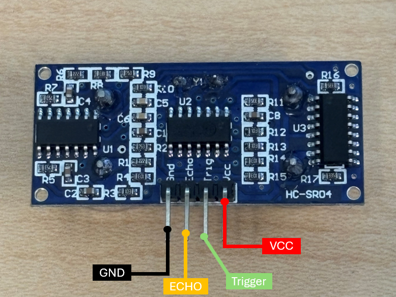
Important: Look up your specific sensors pinout and input voltage as they can differ. The pinout for the sensor we used in this demo was...
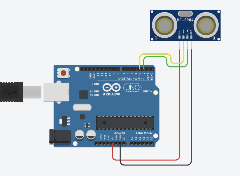
Example circuit setup:
- Ultrasonic sensor output (trig) connected to pin 3, input (echo) connected to pin 2, VCC connected to 5V, and GND (ground) connected to GND.
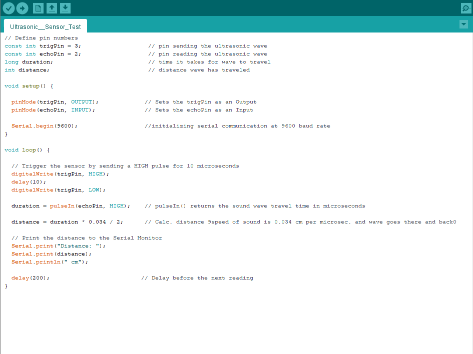
- The code uploaded to the Arduino (below) sets the trigger pin HIGH, emitting a wave, that then returns and is received by the echo pin. Using an equation that utilizes the speed of light we are able to determine the time it takes for the wave to return after being transmitted, giving us our distance.
Troubleshooting
Claire edits:
- If sensor reading 0 only
- Run test code below
- Ensure pin definitions are correct and wires are plugged in to correct spots - If nothing shows up in serial monitor
- Make sure you include Serial.begin(9600);
- Ensure serial monitor has 9600 baud rate selected
Simple Code
// Define pin numbers
const int trigPin = 3; // pin sending the ultrasonic wave
const int echoPin = 2; // pin reading the ultrasonic wave
long duration; // time it takes for wave to travel
int distance; // distance wave has traveled
void setup() {
pinMode(trigPin, OUTPUT); // Sets the trigPin as an Output
pinMode(echoPin, INPUT); // Sets the echoPin as an Input
Serial.begin(9600); //initializing serial communication at 9600 baud rate
}
void loop() {
// Trigger the sensor by sending a HIGH pulse for 10 microseconds
digitalWrite(trigPin, HIGH);
delay(10);
digitalWrite(trigPin, LOW);
duration = pulseIn(echoPin, HIGH); // pulseIn() returns the sound wave travel time in microseconds
distance = duration * 0.034 / 2; // Calc. distance 9speed of sound is 0.034 cm per microsec. and wave goes there and back0
// Print the distance to the Serial Monitor
Serial.print("Distance: ");
Serial.print(distance);
Serial.println(" cm");
delay(200); // Delay before the next reading
}Measuring distance/proximity
If you need to quantify distance:
SHARP 2Y0A02, IR sensor (λ = 850 ± 70nm)
At-a-glance useful details:
- Sensing range: 20 - 150 cm
- Power requirements: 4.5 - 5.5 V (typ current consumption = 33mA)
-
link to datasheet
- Output voltage is not linear with distance; see plot below (from datasheet, linked above)
-


Ultrasonic Sensor (HC-SR04)
These sensors can detect objects within a range of 2 cm - 4 m with a ranging accuracy of up to 3mm. One thing to note is that they have a measure angle of 15 degrees, so they do well at measuring objects directly in front of the sensor. For most applications, this is favorable.
Helpful resource from Sparkfun with example code, and wiring diagram: https://www.sparkfun.com/ultrasonic-distance-sensor-hc-sr04.html
If you just need to know if an object is present or not:
(e.g., detecting fan speed, motion detector, etc.)
Hall Sensor (AH1815, from Treston)
IR LED & transceiver
Two options:
- Single PCB with LED and transceiver
- LED and transceiver from Treston (BYOC or build your own circuit)
Good for:
Detecting a moving object less than few inches away from the sensor
Hall Sensor (AH1815, from Treston)
Overview
Hall sensors are available from the Treston. The presence of a magnetic field switches their output pin (pin 3) from HIGH to LOW.
Detection distance: ~1cm
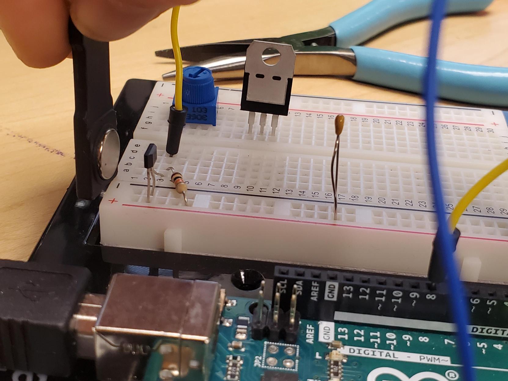
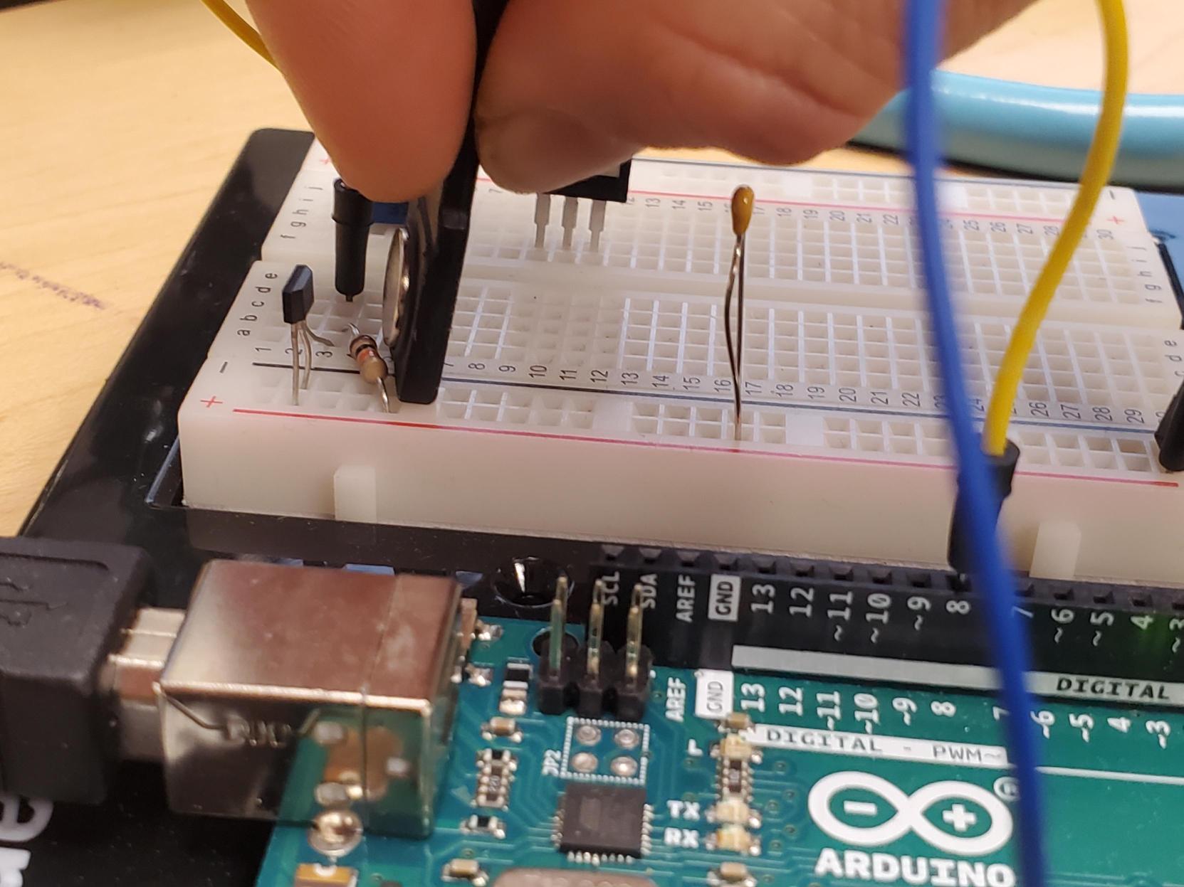
Pictures illustrating short range of sensor
To test the range of the Hall sensor. I used my nametag magnet and held it far away from the sensor. I slowly brought the magnet close until I read a low signal on the digital pin to which I wired the output of this sensor (yellow jumper wire going to Arduino digital pin 8). The images below demonstrate the threshold distance close enough to trigger the sensor, as well as the fact that the sensor detects a field behind or in front of it.
Magnetic field operating point: ~350 Gauss (a cheap kitchen magnet is around 100 Gauss, a strong magnet is 200-2,000 Gauss)
Pinout for the AH1815, note the orientation/non-flat face is up

How to use
You will need to add a pull-up resistor to the output pin. I'd recommend a 10k resistor.

Image above is from this component's data sheet
See if you can wire this circuit just based off of the image above!
Need help?
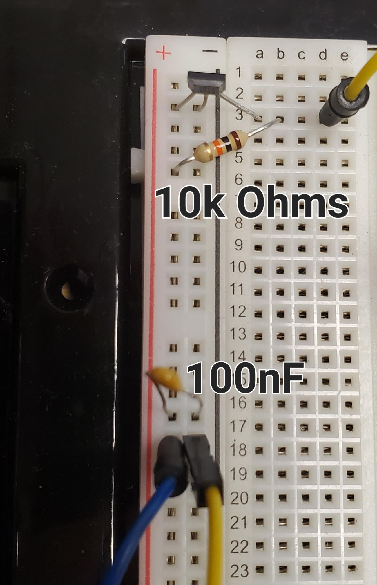
I will show you an image below of how I wired it onto a breadboard. Importantly, you could wire this differently, or solder on longer wires onto each pin of the Hall sensor, or solder this onto a protoboard.
Regardless of whether you are using a breadboard or soldering, you need to make sure that:
- Leftmost pin goes to power (2.5-5.5V input range, so you can use this with a 3.3V microcontroller)
- Middle pin goes to ground
- Rightmost pin goes to a digital pin on your microcontroller
- Add a 10kOhm resistor between power and rightmost (output) pin
- Add a 100 nF capacitor across power and ground to decrease noise
Sample Arduino code
Troubleshooting
1) There's no output when I run the code above
- Make sure you've opened the Serial monitor and the baud rate in the code matches that in the dropdown menu
- Click this:

- Click this:

2) The output bounces all over the place
- Verify that you have the pull-up resistor installed between power and output
- Verify that the value of the pull-up resistor is between 10k and 100kOhms
3) The output thinks there is a magnet there when there isn't
- Verify that a pull-up resistor is present
4) It's too slow
- Decrease the delay(100) to delay(10), etc.